Comparison Of Lcd Display Modules Based On Size And Resolution
You can find a wide range of monochrome lcd display modules on the market, with sizes and resolutions tailored to fit many applications. For quick reference, consider the following common options:
|
Specification |
Example Values |
|---|---|
|
Display Resolution |
128×64, 256×128 |
|
Interface Type |
I²C, SPI, Parallel |
Choosing the right lcd size and resolution impacts display clarity, reliability, and energy efficiency. You should always match the lcd module to your specific use case and performance needs.
Key Takeaways
-
Choose the right LCD size and resolution to enhance display clarity and energy efficiency for your specific application.
-
Small LCD modules (1.54 to 3.5 inches) are ideal for compact devices, providing clear visibility for basic information.
-
Medium LCD modules (4.3 to 7 inches) balance size and readability, making them suitable for industrial and medical applications.
-
Large LCD modules (10.1 inches and above) support complex data presentation, perfect for dashboards and public displays.
-
Understand the differences in LCD technologies (TN, STN, FSTN) to select the best option for your device's performance needs.
Monochrome lcd display size categories
When you select a monochrome lcd display, you need to consider the physical size. The size determines how much information you can show and how the module fits into your device. Manufacturers offer a wide range of lcd sizes to meet different requirements.
Small lcd modules
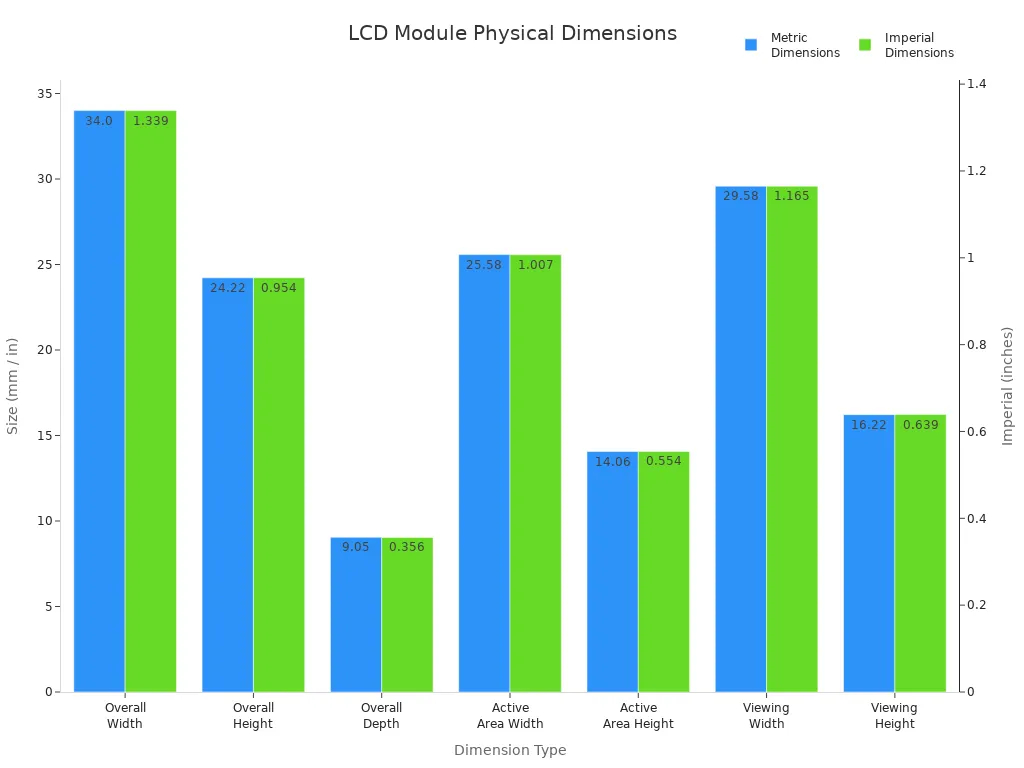
Small lcd modules work best in compact devices. You often see these in wearables, handheld meters, or remote controls. These modules usually measure between 1.54 inches and 3.5 inches diagonally. For example, a typical small lcd module might have the following dimensions:
|
Dimension |
Metric |
Imperial |
|---|---|---|
|
Overall Width |
34.00 mm |
1.339 in |
|
Overall Height |
24.22 mm |
0.954 in |
|
Overall Depth |
9.05 mm |
0.356 in |
|
Active Area Width |
25.58 mm |
1.007 in |
|
Active Area Height |
14.06 mm |
0.554 in |
|
Viewing Width |
29.58 mm |
1.165 in |
|
Viewing Height |
16.22 mm |
0.639 in |
You can use a Mono LCD Segment Display for simple icons or numbers in these small modules. They provide clear visibility in limited space.
Medium lcd modules
Medium lcd modules range from 4.3 inches to 7 inches. You find these in industrial controllers, medical devices, and smart home panels. This size gives you more room for detailed graphics and text. A monochrome lcd display in this category balances compactness with readability. You can also choose a transflective lcd module for better outdoor visibility.
Tip: Medium lcd modules often support higher resolutions, making them suitable for applications that require both clarity and moderate screen size.
Large lcd modules
Large lcd modules include sizes like 10.1 inches, 12.1 inches, and 15.6 inches. You see these in equipment dashboards, large instrumentation panels, and public information displays. A large monochrome lcd display allows you to present complex data or multiple data streams at once. These modules support advanced features and higher resolutions, which enhance user experience in demanding environments.
-
Large lcd modules suit applications where you need maximum visibility and information density.
-
You can integrate these displays into systems that require robust performance and long-term reliability.
By understanding these size categories, you can match the right lcd module to your project’s needs and ensure optimal performance.
Common resolutions in monochrome lcd displays
Monochrome lcd displays come in several standard resolutions. You need to understand how each resolution affects display clarity, content capacity, and application suitability. Manufacturers design lcd modules to match the requirements of different devices and environments.
Low resolution (e.g., 128x64)
You often choose low-resolution lcd modules for simple interfaces. A 128x64 lcd provides basic graphics and text. You see these modules in embedded electronics, DIY projects, and industrial HMI panels. They deliver reliable performance in extreme conditions. You can use a Mono LCD Segment Display for clear numbers and icons. Low-resolution monochrome lcd displays also appear in consumer devices like budget monitors and entry-level TVs. These modules focus on uniform brightness and lower power consumption. The table below shows typical use cases:
|
Use Case Category |
Description |
|---|---|
|
Embedded & DIY electronics |
Used for status readouts and menus in Arduino, Raspberry Pi, and custom PCBs |
|
Industrial HMI |
Deployed in factory panels and medical devices for reliability |
|
Consumer displays |
Found in budget monitors and entry-level TVs |
Note: Low-resolution lcd modules offer better contrast and simple readability. You can rely on them for basic information display.
Medium resolution (e.g., 192x64, 240x64)
Medium-resolution monochrome lcd displays give you more space for detailed content. You can show more text, icons, and simple graphics. These lcd modules fit well in industrial controllers, medical devices, and smart home panels. You benefit from improved clarity and moderate information density. Medium-resolution lcd displays often use Transflective LCD Module technology for better contrast in bright environments. You can select these modules when you need a balance between size and readability.
High resolution (e.g., 240x128, 320x240)
High-resolution monochrome lcd displays allow you to present complex data and fine graphics. You can use these lcd modules in large dashboards, advanced instrumentation, and public information displays. High-resolution lcd modules support multiple data streams and detailed layouts. You gain better contrast and enhanced user experience. These lcd displays suit applications that demand maximum visibility and information density.
Tip: You should match the lcd resolution to your application’s content requirements. Higher resolution means more detail, but also higher power draw.
Monochrome lcds: size and resolution combinations
When you compare monochrome lcd displays, you need to look at how size and resolution pair together. Not every lcd size supports every resolution. Some combinations appear more often because they fit the needs of popular applications. Understanding these pairings helps you choose the right lcd for your project.
Popular pairings
You will notice that certain size and resolution combinations dominate the market. Manufacturers focus on these pairings because they deliver the best balance of readability, cost, and performance for most users. Here are some of the most common options:
|
LCD Size (Diagonal) |
Typical Resolution(s) |
Common Applications |
|---|---|---|
|
1.54" – 2.42" |
128x64 |
Wearables, handheld meters, remote controls |
|
3.5" – 4.3" |
192x64, 240x64 |
Industrial controllers, smart home panels |
|
5.7" – 7.0" |
240x128, 320x240 |
Medical devices, instrumentation panels |
|
10.1" – 15.6" |
320x240, 640x480 |
Dashboards, public information displays |
You often see 128x64 resolution in small lcd modules because it offers clear text and simple graphics in a compact space. Medium lcd modules usually pair with 192x64 or 240x64 for better contrast and more detailed content. Large lcd modules support high resolutions like 320x240, which allow you to display complex data and multiple streams at once.
You can select a Mono LCD Segment Display for simple numeric or icon-based interfaces, especially in small and medium sizes. For applications that require sunlight readability, a Transflective LCD Module provides better contrast and wide viewing angles.
Availability comparison
You will find that not every size and resolution combination is easy to source. Some gaps exist in the market due to manufacturing limitations or low demand. Here is what you should consider:
-
Manufacturers produce most monochrome lcd displays in standard sizes and resolutions. You will find the widest selection in the 128x64 and 240x128 ranges.
-
Fully graphic monochrome lcd displays in large sizes (over 10 inches) with high resolution remain less common. These modules cost more and may require custom orders.
-
Smaller monochrome lcds are generally less expensive. For example, a 2.42-inch monochrome lcd display can cost between $4 and $6. Larger or specialized displays may reach up to $15, but they still cost less than color displays.
-
Transflective monochrome lcd displays offer sunlight readability and wide viewing angles. You can use them in outdoor, industrial, or harsh environments where durability and contrast matter most.
-
Some combinations, such as small lcd modules with very high resolution, are rare. Manufacturers focus on practical pairings that balance clarity, power consumption, and cost.
Note: If you need a unique size or resolution, you may face longer lead times or higher prices. Standard pairings offer better availability and support.
When you choose a monochrome lcd display, always match the size and resolution to your application. Popular combinations ensure you get reliable supply, better contrast, and proven performance.

LCD technology types
When you select a monochrome lcd module, you need to understand the differences in lcd display technology. Each technology impacts performance, viewing angle, and suitability for your application. You can choose from three main types: TN, STN, and FSTN.
TN lcds
Twisted Nematic (TN) lcds use a 90-degree twist in their liquid crystal structure. You often see TN lcds in segment displays and simple monochrome lcd modules. TN lcds deliver fast response times and the lowest cost. You benefit from quick updates, which makes TN lcds ideal for applications where speed matters. However, TN lcds offer narrow viewing angles and lower contrast. You may find TN lcds limited to eight common lines, which restricts their use in complex layouts. TN lcds suit basic Mono LCD Segment Display applications, such as calculators or simple meters.
TN lcds provide reliable performance for entry-level devices. You should consider TN lcds when you need a cost-effective solution and do not require wide viewing angles.
STN lcds
Super-Twisted Nematic (STN) lcds feature a twist angle between 180 and 270 degrees. You gain wider viewing angles and higher contrast compared to TN lcds. STN lcds support multiple display modes, which makes them suitable for portable devices and industrial panels. You can use STN lcds in monochrome lcd displays that require moderate clarity and improved visibility. STN lcds offer medium response times and cost, which balances performance and affordability. You often see STN lcds in Transflective LCD Module products, which enhance readability in bright environments.
STN lcds deliver better color representation and contrast. You should select STN lcds for applications where you need improved readability and moderate information density.
FSTN lcds
Film Super-Twisted Nematic (FSTN) lcds build on STN technology by adding an optical compensating film. You get a true black-and-white display with a white background and black characters. FSTN lcds provide the widest viewing angles and highest contrast among monochrome lcd display technologies. You can achieve a paper-like appearance, which is ideal for medical devices and advanced instrumentation. FSTN lcds offer medium response times and a slightly higher cost. You should choose FSTN lcds when your application demands clear visibility and a professional look.
FSTN lcds excel in environments where clarity and contrast are critical. You can rely on FSTN lcds for high-end monochrome lcd displays that require a true black-and-white display.
|
LCD Type |
Description |
Twist Angle |
Viewing Angle |
Contrast |
Response Time |
Cost |
Key Features |
|---|---|---|---|---|---|---|---|
|
TN |
Twisted Nematic LCD |
90° |
Narrow |
Low |
Fast |
Lowest |
Used for segment displays, limited to 8 common lines |
|
STN |
Super-Twisted Nematic LCD |
180–270° |
Wide |
High |
Medium |
Medium |
Multiple display modes, better contrast |
|
FSTN |
Film Super-Twisted Nematic LCD |
180–270° |
Wider |
Higher |
Medium |
Med-High |
White background, black characters, paper-like display |
You should match the lcd display technology to your application’s requirements. TN lcds fit simple Mono LCD Segment Display needs. STN lcds work well in Transflective LCD Module products for portable and industrial use. FSTN lcds provide the best clarity for advanced monochrome lcd displays.
Application suitability for monochrome lcd displays
Selecting the right monochrome lcd display for your application requires careful consideration of size, resolution, and technology. You need to match these factors to the demands of your device, whether you design wearables, industrial panels, or medical equipment. Golden Vision offers a broad portfolio of monochrome lcds, Mono LCD Segment Displays, and Transflective LCD Modules, making it easier for you to find a solution that fits your requirements.
Wearables and portable devices
You want a display that fits comfortably in compact devices. Small monochrome lcd modules, typically between 1.54 and 2.42 inches, deliver clear information without overwhelming the user interface. Most wearables use 128x64 resolution, which provides crisp text and simple graphics. Mono LCD Segment Displays excel in these environments, showing icons, numbers, and basic status indicators. You benefit from low power consumption and high contrast, which extends battery life and improves readability outdoors.
-
Choose small lcd modules with 128x64 resolution for fitness trackers, smartwatches, and handheld meters.
-
Transflective LCD Modules enhance visibility in sunlight, making them ideal for portable devices used outdoors.
-
Golden Vision’s compact monochrome lcd displays offer reliable performance and easy integration for wearable technology.
Tip: Select a display with a robust enclosure and wide viewing angles to ensure durability and usability in mobile applications.
Industrial and instrumentation panels
Industrial environments demand displays that withstand harsh conditions and deliver precise information. Medium and large monochrome lcd displays, ranging from 3.5 to 6.2 inches, are common in control panels and automation systems. You often see resolutions like 240x320, 320x240, and 640x320, which allow you to present detailed data and multiple parameters at once. High contrast and readability are essential, especially when operators must interpret information quickly.
|
Size (inches) |
Resolution (pixels) |
Typical Use Case |
|---|---|---|
|
3.5 |
240x320 |
Compact control panels |
|
5.7 |
320x240 |
Instrumentation displays |
|
6.2 |
640x320 |
Advanced automation systems |
Monochrome lcd displays dominate industrial panels because they resist glare and maintain clarity under bright lighting. Fully graphic monochrome lcd displays support complex layouts and real-time monitoring. Golden Vision’s Transflective LCD Modules provide wide viewing angles and sunlight readability, making them suitable for both indoor and outdoor installations.
-
Select medium or large lcd modules with higher resolutions for industrial HMI, process control, and instrumentation.
-
Mono LCD Segment Displays work well for simple numeric readouts and status indicators.
-
Golden Vision’s industrial-grade monochrome lcds ensure long-term reliability and high contrast.
Note: You should prioritize displays with rugged construction and extended temperature ranges for demanding industrial applications.
Medical and specialized equipment
Medical devices require displays that meet strict standards for clarity, reliability, and compliance. You need monochrome lcd displays with high resolution and superior contrast to ensure accurate readings and diagnostics. Sizes from 5.7 to 7 inches are typical, with resolutions such as 240x128, 320x240, or higher. Medical displays must maintain luminance over time, feature closed-loop calibration, and meet DICOM part 14 Grayscale Standard for compliance.
|
Aspect |
Medical Displays |
Consumer Displays |
|---|---|---|
|
Luminance |
Designed with headroom for performance decay |
Performance decays significantly over time |
|
Calibration |
Closed-loop control with built-in photometer |
Manual brightness control without reference |
|
Pixel Defects |
Stricter standards for acceptable pixel defects |
Higher tolerance for bad/dead pixels |
|
Lifespan |
Expected to last 5+ years without degradation |
Shorter lifespan with noticeable quality decay |
|
Compliance |
Meets DICOM part 14 Grayscale Standard |
No specific compliance standards |
You should select monochrome lcds with FSTN technology for medical equipment, as these provide true black-and-white displays and wide viewing angles. Golden Vision’s medical-grade monochrome lcd display modules offer extended lifespan and strict quality control, supporting critical applications such as patient monitors, diagnostic instruments, and laboratory devices.
-
Choose large lcd modules with high resolution and strict compliance for medical and specialized equipment.
-
Transflective LCD Modules improve visibility in clinical environments with variable lighting.
-
Mono LCD Segment Displays are suitable for simple numeric or icon-based interfaces in specialized tools.
Alert: Always verify that your display meets medical compliance standards and offers long-term reliability for patient safety.
You can optimize your device’s performance by matching the right monochrome lcd display to your application. Golden Vision’s range covers wearables, industrial panels, and medical equipment, ensuring you find a module that meets your needs for clarity, durability, and compliance.
Pros and cons of size and resolution choices
Small, low-resolution modules
You often select small, low-resolution monochrome lcd displays for compact devices. These modules deliver clear numeric or icon-based information. You benefit from cost effectiveness and power efficiency. Small lcd modules withstand harsh environments and offer sunlight readability. However, you face limitations in visual appeal and information density. Market perception sometimes favors larger, more advanced displays.
|
Advantages |
Disadvantages |
|---|---|
|
Cost Effectiveness |
Limited Visual Appeal |
|
Power Efficiency |
Information Density |
|
Durability |
Market Perception |
|
Sunlight Readability |
|
Mono LCD Segment Display technology fits these modules well. You achieve reliable performance in wearables, meters, and portable devices.
Large, high-resolution modules
Large, high-resolution monochrome lcd displays provide expansive viewing areas and detailed content. You can present complex graphics, multiple data streams, and advanced layouts. These lcd modules enhance user experience in dashboards and medical equipment. You gain better contrast and improved readability. Fully graphic monochrome lcd displays support intricate designs and professional interfaces. However, you encounter higher costs and increased power consumption. Large lcd modules require careful integration and may not suit every application.
Tip: Transflective LCD Module technology improves visibility in bright environments, making large monochrome lcds ideal for industrial and outdoor panels.
Trade-offs and selection tips
You must balance size, resolution, and cost when choosing a monochrome lcd display. Consider these selection tips:
-
For basic numeric or text displays, choose TN lcd technology. You get cost-effective solutions and standard sizes for thermostats and power meters.
-
For simple graphics or menus, select STN lcd technology. You benefit from higher resolution and better visibility in daylight.
-
For high-end or medical devices, opt for FSTN lcd technology. You achieve a professional appearance and clear legibility for analyzers and smart home panels.
Monochrome lcd displays offer flexibility across applications. You should match the lcd module to your device’s requirements. Large lcds with high resolution deliver better contrast and advanced features. Small lcds with low resolution maximize efficiency and durability. Transflective LCD Module and Mono LCD Segment Display technologies enhance usability in specialized environments.
Note: Evaluate your application’s needs before selecting a monochrome lcd. Consider information density, power consumption, and user expectations.
When you select a Monochrome LCD Display, you must consider three factors: size, resolution, and technology type. Each one shapes usability, clarity, and performance.
-
Size determines the number of segments and fits your device’s design.
-
Resolution affects how clear and detailed your information appears.
-
Technology type, such as Mono LCD Segment Display or Transflective LCD Module, impacts power use and application suitability.
You should always match display size and resolution to your project’s needs. The table below shows how this improves user experience:
|
Size/Resolution Options |
Benefits for User Experience |
|---|---|
|
Diverse range available |
Tailored visibility and readability |
|
Customization options |
Meets specific project requirements |
For battery-powered or outdoor devices, prioritize low power and sunlight readability. If your design cannot fit standard sizes, consider custom modules.
FAQ
What factors should you consider when choosing a Monochrome LCD Display?
You should evaluate size, resolution, and technology type. Match the display to your device’s requirements. Consider clarity, power consumption, and application environment for optimal performance.
How does a Mono LCD Segment Display differ from a graphic LCD?
A Mono LCD Segment Display shows fixed icons or numbers. You use it for simple readouts. Graphic LCDs display variable content, including text and images, offering greater flexibility.
Can you use a Transflective LCD Module outdoors?
Yes, you can use a Transflective LCD Module in outdoor environments. It provides excellent sunlight readability and wide viewing angles, making it ideal for portable and industrial devices.
Which applications benefit most from high-resolution Monochrome LCD Displays?
Medical equipment, advanced instrumentation, and dashboards benefit from high-resolution Monochrome LCD Displays. You gain detailed graphics, clear data presentation, and improved user experience.
Are custom sizes available for Monochrome LCD Displays?
Manufacturers offer custom sizes for Monochrome LCD Displays. You can request unique dimensions or resolutions to fit your project. Custom modules may require longer lead times and higher costs.