The bathroom is a room that we spend a lot of time in for the morning and for the evening, so it's important to make it a space that we enjoy being in. A lighted LED vanity mirror is a great way to do that. It can provide a warm and welcoming glow, and it can also be a functional addition to the space.


Metal framed LED mirror
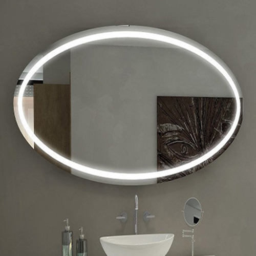
Oval LED mirror bathroom

When there are no shadows, you can see your face clearly, which helps you choose the right makeup colors and hair style.


LED lighting is a win for everybody. They are cheaper, last longer, and use less energy than its traditional counterparts.


A bathroom LED mirror often has an anti-fog function, which prevents it from fogging up when you take a shower.


LED mirrors can be dimmable and changed to different colors, they're helpful for different tasks such as applying makeup or shaving.


The electric LED vanity mirror is typically water-resistant construction, which makes them ideal for bathrooms.


In addition to having great functions, vanity mirrors with LED lights come in various shapes and styles, making them a flexible choice for vanity mirror design. We've created a comprehensive guide to help you find the LED mirror that best fits your decor and needs.


If you would like any further information, please feel free to contact our advisor via sales@sunwinhotellighting.com - we're always happy to help! Sunwin is one of the famous China LED bathroom mirror factories, has over 17 years' rich experience on custom lighted mirrors.


What Are the Advantages of Using A Hybrid PCB with RO4003C and S1000-2M Materials?


Introduction:

In the fast-paced world of electronics, the demand for high-frequency and low-loss circuit boards continues to drive innovation. To meet these requirements, we present our newly shipped Hybrid PCB, incorporating the advanced materials RO4003C and S1000-2M. Designed for superior performance and cost-effective fabrication, this 6-layer PCB offers exceptional characteristics for RF microwave circuits, matching networks, and controlled impedance transmission lines. In this blog, we delve into the features, construction details, and potential applications of this cutting-edge hybrid PCB.


1. Introduction to RO4003C:

Rogers RO4003C materials are a breakthrough in PCB technology, combining the excellent electrical properties of PTFE/woven glass with the manufacturing feasibility of epoxy/glass. The result is a low-loss material that can be fabricated using standard epoxy/glass (FR-4) processes at competitive prices. With its unique composition, Rogers RO4003c PCB offers superior high-frequency performance and opens up new possibilities for RF microwave circuit design.


RO4003C Substrate are specifically tailored to meet the needs of high-frequency designers, providing low dielectric loss and enabling applications that were previously limited due to operating frequency constraints. Furthermore,RO4003C laminates utilize various configurations, all of which meet the same electrical performance specifications. It is important to note that these materials are non-brominated and not UL 94 V-0 rated, making them an environmentally friendly choice.


Hybrid PCB on RO4003C and S1000-2M 6-layer


2. Features of RO4003C:

2.1 Dielectric Properties:

RO4003C exhibits impressive dielectric properties that contribute to its exceptional performance:


- Dielectric Constant (DK):

Primarily measured at 3.38 +/- 0.05 at 10GHz, this property ensures stable signal propagation throughout high-frequency applications.


- Dissipation Factor:

With a value of 0.0027 at 10GHz, RO4003C minimizes signal loss, enabling efficient signal transmission.


- Thermal Conductivity:

The material's thermal conductivity is 0.71 W/m/°K, facilitating effective heat dissipation within the PCB.


- Thermal Coefficient of Dielectric Constant:

RO4003C exhibits a negligible variation in dielectric constant over a wide temperature range, demonstrating stability and reliability.


- CTE Matched to Copper:

The material showcases a CTE matched to copper, with X-axis at 11 ppm/°C and Y-axis at 14 ppm/°C.


- Low Z-Axis Coefficient of Thermal Expansion:

RO4003C maintains a low coefficient of thermal expansion, measured at 46 ppm/°C.


- High Glass Transition Temperature (Tg):

The Tg of RO4003C exceeds 280°C, ensuring excellent thermal stability even under demanding conditions.


- Low Moisture Absorption:

RO4003C has a low moisture absorption rate of 0.06%, preventing performance degradation caused by humidity.


2.2 Features of S1000-2M:

The S1000-2M substrate, combined with RO4003C, enhances the Hybrid PCB's performance further:


- Lower Z-Axis CTE:

The S1000-2M exhibits a lower coefficient of thermal expansion, significantly improving trough-hole reliability.


- Excellent Mechanical Processability and Thermal Resistance:

S1000-2M offers superior mechanical processability, making it ideal for various manufacturing processes. It also exhibits exceptional thermal resistance, ensuring reliable functionality under demanding operating conditions.


- Lead-free Compatibility:

With lead-free compatibility, the PCB meets environmental standards and supports future sustainability goals.


- High Heat Resistance:

S1000-2M possesses high heat resistance, enabling reliable operation under elevated temperature scenarios.

- Excellent Anti-CAF (Conductive Anodic Filament) Performance:

The material's anti-CAF properties prevent conductive filament formation, enhancing long-term reliability.


- Low Water Absorption:

S1000-2M exhibits low water absorption, protecting the PCB's electrical characteristics from moisture-related issues.


What are the advantages of using a Hybrid PCB with RO4003C and S1000-2M materials?


High Frequency Performance:

RO4003C is a high-frequency laminate material known for its excellent electrical properties. It offers low insertion loss, low dielectric constant, and tight control over impedance, making it ideal for applications that require high-frequency performance. S1000-2M, on the other hand, is a versatile material with good electrical properties, suitable for RF and microwave applications.


Design Flexibility:

Hybrid PCB Material allow for the combination of different materials to optimize the board's performance. By using RO4003C and ShengyiS1000-2M materials together, designers can take advantage of the unique properties of each material to achieve specific design goals. This combination provides flexibility in designing circuits with different impedance requirements and can help achieve higher performance.


Cost Optimization:

Hybrid circuit materials PCBs offer the opportunity to optimize costs while maintaining performance requirements. By strategically using RO4003C and S1000-2M materials, designers can allocate the high-performance material where it's most needed while using the cost-effective material in less critical areas. This approach helps balance the overall cost of the PCB without compromising performance.


Thermal Management:

RO4003C and S1000-2M materials have different thermal properties. By using a hybrid PCB with these materials, designers can benefit from improved thermal management. They can strategically place components on the board to leverage the different thermal conductivity and heat dissipation capabilities of the materials, ensuring optimal thermal performance.


Reliability and Durability:

Both RO4003C and S1000-2M materials are known for their reliability and durability. Hybrid PCBs using these materials can withstand harsh operating conditions, such as high temperatures and high-frequency signals, while maintaining their electrical performance and mechanical integrity over time. This ensures a longer lifespan and higher reliability of the overall electronic system.


Miniaturization:

The combination of RO4003C and S1000-2M materials enables the design of compact and miniaturized electronic systems. RO4003C offers excellent electrical properties in a thin form factor, allowing for high-density circuit designs. S1000-2M, with its versatile characteristics, complements the design by providing a cost-effective material for less critical areas, enabling further miniaturization of the overall PCB assembly.


These advantages make hybrid PCBs with RO4003C and S1000-2M materials an attractive choice for applications such as telecommunications, aerospace, automotive, and high-speed digital circuits that require high-frequency performance, reliability, cost-optimization, and thermal management.


3. PCB Stackup:

The Hybrid PCB features a 6-layer pcb stackup that optimizes signal integrity and reliability:


- Copper Layer 1: 35μm

- RO4003C: 0.305 mm (12 mil)

- Copper Layer 2: 35μm

- Prepreg: 1080 RC63% 0.0644 mm (2.5 mil)

- Copper Layer 3: 35μm

- S1000-2M: 0.203 mm (3 mil)

- Copper Layer 4: 35μm

- Prepreg: 1080 RC63% 0.0644 mm (2.5 mil)

- Copper Layer 5: 35μm

- RO4003C: 0.305 mm (12 mil)

- Copper Layer 6: 35μm


4. Artwork and Standard Compliance:

The Hybrid PCB complies with industry-standard specifications and is designed for ease of use:


- Artwork Format:

Gerber RS-274-X artwork ensures compatibility and allows for seamless integration into existing design workflows.


- Accepted Standard:

The Hybrid PCB adheres to the IPC-Class-2 standard, guaranteeing reliability and interoperability.


- Worldwide Availability:

This groundbreaking Hybrid PCB is available for purchase worldwide, ensuring accessibility for customers across the globe.


5. Typical Applications:

The Hybrid PCB excels in a wide range of applications, including but not limited to:


- Commercial Airline Broadband Antennas:

The PCB offers exceptional performance in the demanding environments of commercial aircraft.


- Microstrip and Stripline Circuits:

With its low dielectric loss and controlled impedance characteristics, the PCB enables precise transmission line design.


- Millimeter Wave Applications:

The Hybrid PCB facilitates the development of millimeter wave systems, achieving high-frequency performance and reliability.


- Radar Systems:

The PCB's properties make it an ideal choice for radar systems that require accurate signal transmission and low loss.


- Guidance Systems:

The high-performance capabilities of the Hybrid PCB contribute to reliable guidance systems in various industries.


- Point-to-Point Digital Radio Antennas:

The PCB provides the necessary characteristics for efficient point-to-point digital radio communication.


Conclusion

The Hybrid PCB Board featuring the RO4003C and S1000-2M materials offers outstanding performance and reliability for high-frequency applications. With the capabilities of the RO4003C material combined with the benefits of the S1000-2M material, this 6 layer board PCB provides unparalleled flexibility, signal integrity, and thermal management. From commercial airline antennas to guidance systems, thishybrid circuit board caters to a wide array of applications. Experience the power of hybrid technology by integrating our advanced Hybrid PCB into your designs and unlock the next level of electronic performance.


What Are the Benefits of Using IsoClad 933 PCB?


In the ever-evolving world of electronics, the demand for high-performance, reliable, and versatile printed circuit boards (PCBs) is at an all-time high. Enter the IsoClad 933 PCB, a cutting-edge solution designed to meet the rigorous demands of modern applications. Whether you're working on conformal antennas, radar systems, or electronic warfare systems, the IsoClad 933 31mil PCB is engineered to deliver exceptional performance, durability, and precision.


In this deep dive, we’ll explore the features, benefits, construction details, and applications of the IsoClad 933 PCB, showcasing why it’s a good PCB in the PCB industry.


Introduction to IsoClad 933: The Foundation of Innovation

Rogers Corporation, a global leader in advanced materials, has once again raised the bar with its IsoClad 933 laminates. These laminates are non-woven fiberglass/PTFE (polytetrafluoroethylene) composites specifically designed for use as PCB substrates. What sets IsoClad 933 apart is its unique non-woven reinforcement, which provides unparalleled flexibility and conformability. This makes it an ideal choice for applications where the final circuit may need to adapt to complex shapes or environments.


The proprietary manufacturing process of Rogers IsoClad 933 incorporates longer random fibers, resulting in superior dimensional stability and enhanced mechanical strength. These properties make it a reliable substrate for high-frequency and high-performance applications, ensuring consistent performance even under challenging conditions.


Key Features of IsoClad 933 PCB

The IsoClad 933 Rogers PCB is packed with features that make it stand out in the competitive PCB market. Here’s a closer look at what makes this product exceptional:


1. Exceptional Electrical Properties

-Dielectric Constant (Dk): 2.33 at 10GHz/23°C

The low and stable dielectric constant ensures minimal signal loss, making it ideal for high-frequency applications.


-Dissipation Factor (Df): 0.0016 at 10GHz/23°C

The low dissipation factor translates to reduced signal attenuation, ensuring efficient signal transmission.


2. Mechanical Strength and Durability

-Peel Strength: 10 lbs. per inch

This high peel strength ensures robust bonding between layers, enhancing the PCB’s durability.


-Low Water Absorption: 0.05%

The low water absorption rate makes it suitable for use in humid or moisture-prone environments.


3. Dimensional Stability

The non-woven fiberglass reinforcement provides excellent dimensional stability, reducing the risk of warping or deformation during manufacturing or operation.


4. Low Outgassing

Total Mass Loss (TML): 0.03%

Collected Volatile Condensable Materials (CVCM): 0%

Water Vapor Regained (WVR): 0.02%


These low outgassing properties make IsoClad 933 suitable for aerospace and satellite applications, where outgassing can compromise performance.


5. Great Dk Uniformity

The consistent dielectric constant across the board ensures reliable performance across a wide range of frequencies.


IsoClad 933 high frequency PCB 


Benefits of IsoClad 933 PCB

The IsoClad 933 31mil Rogers substrate PCB isn’t just about features; it’s about delivering tangible benefits to engineers, designers, and end-users. Here’s what you can expect:


1. Flexibility and Conformability

Unlike traditional woven fiberglass PCBs, IsoClad 933 is less rigid, making it ideal for applications requiring conformability. This flexibility opens up new possibilities for innovative designs, particularly in conformal antennas and wearable electronics.


2. High Isotropy

The material is highly isotropic in the X, Y, and Z axes, ensuring uniform performance regardless of the direction of signal propagation.


3. Stable Dk Over a Range of Frequencies

The stable dielectric constant across frequencies ensures consistent performance, making it suitable for broadband applications.


4. Improved Dimensional Stability

The enhanced dimensional stability reduces the risk of manufacturing defects, ensuring higher yields and lower costs.


5. Versatility

From aerospace to telecommunications, the IsoClad 933 PCB is versatile enough to meet the demands of a wide range of industries.


PCB Construction Details

The IsoClad 933 PCB is meticulously crafted to meet the highest standards of quality and performance. Here’s a breakdown of its construction:


PCB Stackup

Layer 1: Copper (35μm)

Core: Rogers IsoClad 933 (0.787 mm / 31 mil)

Layer 2: Copper (35μm)


PCB Construction

Board Dimensions: The IsoClad 933 PCB comes in a standard size of 70.07mm x 58.31mm, allowing for versatile use across various applications. The dimensions are precise, with a tolerance of +/- 0.15mm.


Minimum Trace/Space: The PCB supports a minimum trace/space of 5/4 mils, enabling precise routing of high-density circuitry and enhancing overall design flexibility.


Minimum Hole Size: The IsoClad 933 PCB accommodates a minimum hole size of 0.3mm, ensuring compatibility with a wide range of components and facilitating efficient assembly processes.


Finished Board Thickness: The finished thickness of the IsoClad 933 PCB is 0.9mm, striking the perfect balance between robustness and compactness.


Finished Cu Weight: The outer layers of the PCB feature a finished copper weight of 1oz (1.4 mils), providing an ideal balance between conductivity and manufacturability.


Via Plating Thickness: The via plating thickness of the IsoClad 933 PCB is 20μm, ensuring reliable electrical connectivity throughout the circuit.


Surface Finish: The PCB is treated with immersion tin, offering excellent solderability and preserving the copper pads from oxidation.


Silkscreen and Solder Mask: The IsoClad 933 PCB comes with a top silkscreen in white, providing clear component labeling. It features a blue top solder mask, protecting the copper traces and ensuring easy inspection.


100% Electrical Test: Prior to shipment, each IsoClad 933 PCB undergoes a rigorous 100% electrical test, ensuring that it meets the specified performance parameters and adheres to the highest standards of quality.


PCB Statistics

The IsoClad 933 PCB demonstrates its versatility and adaptability through its wide range of statistics:

Components: The PCB can accommodate up to 19 components, offering ample space for various functionalities and circuitry requirements.


Total Pads: With a total of 52 pads, the IsoClad 933 PCB enables efficient connectivity and integration of components.


Thru-Hole Pads: The PCB provides 25 via pads for through-hole components, facilitating robust and reliable connections.


Top SMT Pads: With 27 surface-mount technology (SMT) pads on the top layer, the IsoClad 933 PCB complements modern assembly techniques and enables compact designs.


Bottom SMT Pads: The PCB has no SMT pads on the bottom layer, making it suitable for applications where components are primarily mounted on the top layer.


Vias: The IsoClad 933 PCB features 17 vias, enabling seamless through-hole connections between different layers of the circuit.


Nets: The PCB supports 2 nets, ensuring efficient signal routing and effective connectivity.


Typical Applications

The IsoClad 933 high frequency PCB is designed to excel in a variety of high-performance applications. Here are some of the most common use cases:


1. Conformal Antennas

The flexibility and conformability of IsoClad 933 make it an excellent choice for conformal antennas, which are often used in aerospace and defense applications.


2. Stripline and Microstrip Circuits

The stable dielectric constant and low dissipation factor make it ideal for stripline and microstrip circuits, ensuring minimal signal loss and high efficiency.


3. Guidance Systems

The high mechanical strength and dimensional stability of IsoClad 933 make it suitable for guidance systems, where precision and reliability are critical.


4. Radar and Electronic Warfare Systems

The low outgassing and excellent electrical properties make it a preferred choice for radar and electronic warfare systems, where performance under extreme conditions is a must.


Why Choose IsoClad 933 PCB?

In a market flooded with options, the IsoClad 933 PCB stands out for its unique combination of flexibility, durability, and performance. Whether you’re designing cutting-edge electronics for aerospace, defense, or telecommunications, this PCB offers the reliability and versatility you need to bring your vision to life.


With its advanced features, robust construction, and proven performance, the IsoClad 933 PCB is more than just a component—it’s a foundation for innovation.


Conclusion

The IsoClad 933 high frequency circuit board is a testament to Rogers Corporation’s commitment to pushing the boundaries of what’s possible in PCB technology. Its unique blend of flexibility, stability, and performance makes it an indispensable tool for engineers and designers working on the next generation of electronic devices.


Whether you’re developing conformal antennas, radar systems, or guidance systems, the IsoClad 933 PCB is ready to meet your most demanding requirements. Explore the possibilities today and experience the difference that advanced materials and superior engineering can make.


Availability: Worldwide

Artwork Format: Gerber RS-274-X

Quality Standard: IPC-Class-2


For more information or to place an order, contact us today and let us help you take your projects to the next level with the IsoClad 933 PCB!

What Is IT-180 Material, and Why Is It Used in PCBs?


In today’s fast-paced technological landscape, the demand for high-performance, reliable, and durable printed circuit boards (PCBs) is greater than ever. Whether you’re designing cutting-edge automotive systems, robust networking equipment, or high-speed telecommunications devices, the foundation of your success lies in the quality of your PCB. That’s why we’re excited to introduce our newly shipped 12-Layer Through-Hole IT-180 Material PCB, a state-of-the-art solution engineered to meet the most demanding requirements of modern electronics.  


This 12 layers PCB is designed with precision, utilizing advanced materials and manufacturing techniques to deliver exceptional performance, thermal reliability, and impedance control. Let’s dive deep into the features, specifications, and applications of this remarkable product.  


1. Material Excellence: IT-180A FR-4 Tg170°C

The backbone of this PCB is the IT-180A material, a high-performance epoxy resin with a glass transition temperature (Tg) of 170°C. This material is specifically designed to handle high thermal stress, making it suitable for lead-free assembly processes and applications exposed to elevated temperatures.


Key features of IT-180A include:


-High Thermal Reliability: Withstands T260 >60 minutes and T288 >20 minutes, ensuring durability during reflow soldering.


-Low Moisture Absorption: At just 0.1%, it minimizes the risk of delamination or electrical failure in humid environments.


-CAF Resistance: Excellent resistance to conductive anodic filament (CAF) formation, enhancing long-term reliability.


-UL 94-V0 Flammability Rating: Meets stringent safety standards for fire resistance.


2. Impedance Control for Signal Integrity

Signal integrity is paramount in high-speed applications, and this PCB delivers with precise impedance control. The board supports multiple impedance values:


-50ΩDifferential Pairs: Optimized for high-speed data transmission.


-90Ωand 100ΩDifferential Pairs: Ideal for differential signaling in communication protocols like USB, HDMI, and Ethernet.


The impedance-controlled traces are meticulously designed with specific trace widths, gaps, and reference layers to ensure minimal signal loss and crosstalk.


12-layer Through Holes PCB 1.6mm IT-180 Impedance Matt Red PCB


3. Robust Construction and Stack-Up

The 12-layer stack-up is a masterpiece of engineering, balancing signal integrity, thermal management, and mechanical strength. Here’s a breakdown of the stack-up:


12-layer stack-up


This symmetrical stack-up ensures even distribution of thermal and mechanical stress, reducing the risk of warping or delamination.


4. Advanced Via Technology

The multilayer printed circuit board features plated through-holes (PTH) spanning all 12 layers, ensuring reliable electrical connections. Additionally, all 0.2mm and 0.3mm vias are filled and capped according to IPC 4761 Type VII, enhancing mechanical strength and solderability.


5. Solder Mask and Silkscreen

The multilayer circuit boards are coated with a matt red solder mask on both sides, providing excellent protection against oxidation and solder bridging. A white silkscreen on the top side ensures clear component labeling and assembly guidance.


Key Features and Benefits

1. High Thermal Performance

With ahighTg 170°Cand excellent thermal resistance, this PCB is built to handle high-temperature environments, making it ideal for automotive and industrial applications.


2. Superior Signal Integrity

The impedance-controlled design minimizes signal loss and crosstalk, ensuring reliable performance in high-speed data transmission.


3. Durability and Reliability

The use of IT-180A material, combined with advanced via filling and capping, ensures long-term reliability even in harsh conditions.


4. Compliance with Industry Standards

The PCB meets IPC-Class-2 standards, ensuring high-quality manufacturing and performance.


Applications of the 12-Layer Through-Hole PCB

This PCB is versatile and suitable for a wide range of high-performance applications, including:


1. Automotive Electronics

Engine room ECUs

Advanced driver-assistance systems (ADAS)

Infotainment systems


2. Telecommunications

5G infrastructure

Base stations

Network routers and switches


3. Data Storage and Servers

High-speed data storage systems

Server motherboards

Network attached storage (NAS) devices


4. Industrial Equipment

Automation systems

Power supplies

Control panels


Why Choose This PCB?

The 12-Layer Through-Hole PCB is more than just a circuit board—it’s a solution engineered for excellence. Here’s why it stands out:


Advanced Material: IT-180A ensures high thermal and mechanical performance.


Precision Engineering: Impedance control and symmetrical stack-up guarantee signal integrity.


Global Availability:Ready to ship worldwide, meeting your production timelines.


Compliance and Quality:Adherence to IPC-Class-2 standards ensures reliability.


Conclusion

In a world where technology is constantly evolving, the 12-Layer Through-Hole PCB sets a new standard for performance, reliability, and versatility. Whether you’re designing cutting-edge automotive systems, high-speed telecommunications infrastructure, or robust industrial equipment, this PCB is your trusted partner.


With its advanced materials, precise impedance control, and robust construction, it’s not just a PCB—it’s the foundation of innovation.


Ready to elevate your designs? Contact us today to learn more about the 12-Layer Through-Hole PCB and how it can power your next project.


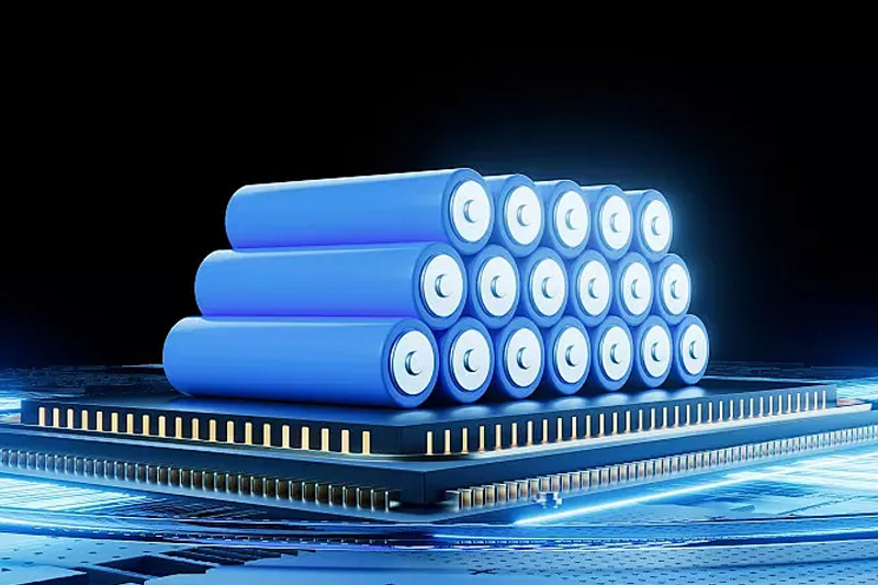
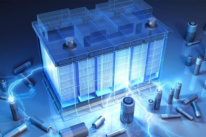
It’s likely that many of the electronic devices in your home today are powered by lithium-ion batteries. Lithium-ion batteries are found in everything from cell phones and children’s toys to power tools, e-bikes, and even electric cars. These rechargeable batteries are ideal for electronic devices that need to efficiently release large amounts of power in a short period of time, and they are more environmentally friendly and cost-effective than disposable batteries. However, if lithium-ion batteries overheat, become damaged, or are exposed to salt water, they can catch fire and explode.


Lithium-ion battery


You may have noticed that there have been many news reports about lithium-ion battery fires in recent years. For example, in 2024, after Hurricanes Helene and Milton, salt water came into contact with lithium-ion batteries in electric vehicles and other battery-powered devices such as golf carts and scooters, causing several house fires. If you’ve flown in recent years, you may have also noticed that carrying a spare lithium-ion battery with you has become a requirement for aviation safety. These incidents have heightened public awareness of lithium-ion batteries, but the actual fire risks are not fully understood by everyone.


Why are lithium-ion batteries so popular?

One significant advantage of lithium-ion batteries is that they allow for more compact devices. Lithium is the lightest metal element, which allows lithium-ion batteries to store more energy in a relatively small space, making for smaller, lighter electronic devices. For portable devices like mobile phones, lightness and compactness are the top consumer demands.

In addition, the rechargeable nature of lithium-ion batteries also makes them more attractive than traditional disposable batteries. Not only can consumers reduce the hassle of frequently purchasing new batteries, but lithium-ion batteries also have no "memory effect." This is different from other types of rechargeable batteries (such as nickel-cadmium batteries), which can cause capacity and voltage to drop if they are recharged without being fully discharged. Lithium-ion batteries avoid this problem, ensuring longer-term efficiency.


Are lithium-ion batteries a fire hazard?


Lithium-ion battery


Lithium-ion batteries are generally safe if they are stored, used, and charged properly. To ensure safety, follow these recommendations when using lithium-ion batteries:

• Store batteries in a cool, dry place away from flammable items and avoid moisture. Do not expose batteries to sunlight or extreme cold.

• Follow the battery storage guidelines provided by the device manufacturer.

• Always use the charger that came with the device. Some chargers have a temperature-regulating feature to ensure that the battery doesn't overheat. Using an inappropriate charger can cause the battery to overcharge, which can pose a safety hazard.

• Always unplug the power cord after charging is complete to avoid overcharging.

• Do not charge your device in bed or under a pillow, and ensure that there is enough air circulation around the device to keep it cool.

Also, lithium-ion batteries don't last forever. Typically, they last two to three years, or about 500 charge and discharge cycles. Common signs of battery aging include slower charging, overheating, swelling, or losing power when not in use. If these problems occur, the battery should be replaced as soon as possible, and never replace a lithium-ion battery yourself without the manufacturer's guidance.


What causes lithium-ion battery fires?

The root cause of lithium-ion battery fires is a phenomenon called "thermal runaway." When the battery cannot effectively release the heat it generates, its temperature rises rapidly, causing a fire or explosion. Counterfeit batteries are a greater risk because they are usually of poor quality and prone to this problem.

Here are some factors that can cause lithium-ion battery fires:

• Leaving the battery plugged in after charging is complete

• Physical damage to the battery or its casing

• Using a charging method that is too fast (usually with a non-designated charger)

• Exposing the battery to extreme heat or cold

• Exposing the battery to salt water, such as when stored in a basement or garage that could be flooded

• Using uncertified batteries


As electric scooters, electric bikes, and other mobility devices become more popular, many fires caused by lithium-ion batteries have occurred in these devices. Residents living in multi-unit housing, especially those who need to charge these battery-powered devices at home, are at an increased risk of fire.

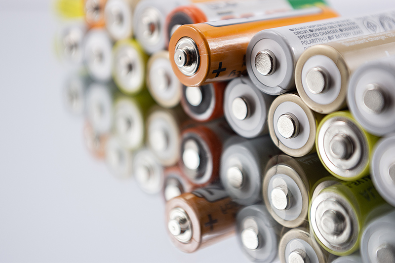
As I continue to work with alkaline batteries, I’m increasingly impressed by their performance. Despite their small size, these batteries are packed with power, making them a modern marvel. When paired with cutting-edge LED technology, a couple of AA alkaline cells can provide hours of bright light. Even in more demanding applications, such as two-way radios, alkaline batteries can outlast rechargeable alternatives, providing long-lasting power for communications.


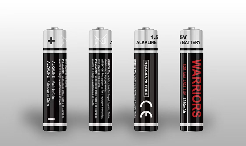
alkaline batteries


One of the most surprising revelations comes from the fact that twelve D alkaline batteries can power a medical suction device for anywhere from six to nine hours. This impressive power density—storing a significant amount of energy in a small, compact form—is one of the main reasons alkaline batteries can serve such a wide variety of functions.


Long Shelf Life: A Key Advantage

Another remarkable feature of alkaline batteries is their long shelf life. These batteries typically remain viable for up to ten years after manufacture, which is why many people stockpile them for emergency preparedness. If you ever check the expiration date on a pack of alkaline batteries, you’ll notice this impressive shelf life. However, it's important to note that while they may still be good after a decade, their capacity will often decrease. By the tenth year, a battery may retain only around 50% of its original capacity, meaning that while they will still work, they won’t last as long in devices.

If you're saving batteries for a critical use, it’s a good idea to ensure that they aren’t too far past their expiration date. Ideally, you want to have at least seven years before they expire. But don’t let your alkaline batteries go to waste. As they near their expiration, you can cycle them into less critical applications, saving your new batteries for essential uses. This helps ensure that you’re not discarding potentially useful power.


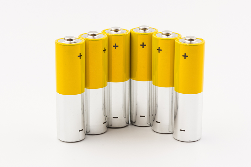
alkaline batteries


The Availability and Versatility of Alkaline Batteries

Alkaline batteries are also incredibly ubiquitous. As one emergency preparedness expert put it, "You can hardly throw a rock without hitting a place that sells alkaline batteries." This is a massive advantage during emergencies when normal supply chains may be disrupted. In fact, alkaline batteries are among the first supplies to be airlifted into disaster-stricken areas, ensuring that essential equipment remains operational.

Recognizing these advantages, manufacturers of medical devices, like Powered Air Purifying Respirators (PAPR), have started to offer alternatives powered by alkaline batteries. These devices, which protect healthcare workers from contaminants, no longer require external power sources or proprietary rechargeable batteries. Similarly, medical aspirators that run on standard D-cell batteries are now available, providing more flexibility in emergency and remote environments.


The Quality Variance in Alkaline Batteries

That said, not all alkaline batteries are created equal. During testing for a medical aspirator powered by alkaline batteries, we discovered significant differences in performance across brands. A reliable rule of thumb is to always choose well-known, trusted brands for alkaline batteries. Generic or off-brand batteries tend to have lower capacity and shorter run times, which can be critical when the battery life is a key factor in your device's performance.


Conclusion

Alkaline batteries remain a staple in both everyday and emergency use due to their impressive energy density, long shelf life, and broad availability. Whether you're powering simple household devices or critical medical equipment, their reliability makes them an excellent choice. Just remember to check the expiration dates, cycle older batteries into less demanding tasks, and always go for reputable brands for the best results.


If you have any devices you'd like to see powered by alkaline batteries, feel free to let us know!

Carbon-zinc batteries and alkaline batteries are two common choices when it comes to choosing a battery. Many people struggle before buying: which battery is better? Each of these two batteries has different characteristics and is suitable for different devices and uses. Understanding the differences between them can help you make a better choice and save you time and money.


What is a carbon-zinc battery?


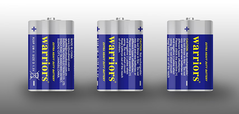
Carbon-zinc batteries


Carbon-zinc batteries (also known as zinc-carbon batteries) are dry cells that provide direct current and are widely used in many small devices. Common devices include remote controls, alarm clocks, flashlights, and fire alarms. These batteries are usually used for short-term applications with low power consumption, suitable for devices that do not require long-term high-power power supply. However, because zinc degrades over time, carbon-zinc batteries may leak electricity, so they need to be checked and replaced regularly.


It is worth noting that carbon-zinc batteries cannot be recharged. Once they are exhausted, they must be properly disposed of in accordance with relevant regulations and cannot be recharged. Otherwise, they may cause safety issues such as explosion.


What is an alkaline battery?


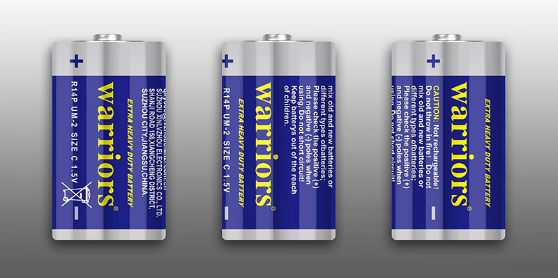
alkaline battery


Alkaline batteries are a more common and powerful battery than carbon-zinc batteries. They are often used in devices that require longer power supply, such as game controllers, cameras, toys, etc. The electrolyte of alkaline batteries is potassium hydroxide, which makes them more advantageous in performance than carbon-zinc batteries. Alkaline batteries have a longer service life and higher voltage, and can usually be used for a longer period of time.


The main difference between carbon-zinc batteries and alkaline batteries

  • Electrolyte type: Carbon-zinc batteries use zinc chloride as the electrolyte, while alkaline batteries use potassium hydroxide. This difference makes the battery performance and service life of the two batteries different.
  • Service life: Carbon-zinc batteries can usually be used for about 18 months, while alkaline batteries can last for about 3 years, suitable for long-term low-power applications.
  • Time and stability of power supply: Alkaline batteries provide a longer and stable power supply than carbon-zinc batteries, especially in devices with higher requirements for battery capacity and stability.


Comparison of prices between carbon-zinc batteries and alkaline batteries

Due to their stronger performance and longer service life, alkaline batteries are usually slightly more expensive than carbon-zinc batteries. However, considering the performance advantages in long-term use, alkaline batteries tend to be more cost-effective.


Comparison of Lithium Batteries and Alkaline Batteries


Lithium Batteries


Although alkaline batteries are better than carbon-zinc batteries, the advantages of lithium batteries are more obvious when compared with lithium batteries. Lithium batteries have a higher energy density than alkaline batteries, which makes them superior in size, weight and performance. The voltage of lithium batteries is generally 3.7V, which is much higher than the 1.5V of alkaline batteries. In addition, lithium batteries have a wider operating temperature range and can provide stable power supply under extreme environmental conditions.


In addition, lithium batteries are more environmentally friendly and have a longer life than alkaline batteries, making them a more efficient and environmentally friendly battery choice.


carbon-zinc batteries


Summary

In general, alkaline batteries have a longer service life and more stable performance than carbon-zinc batteries, and are suitable for devices that require long-term power supply. Although alkaline batteries are slightly more expensive, in many cases, choosing alkaline batteries will be more economical and practical.


If the performance requirements of the battery are higher or it needs to be used in extreme environments, lithium batteries are a better choice. It not only provides higher voltage and longer life, but also has obvious advantages in environmental protection and efficiency. Ultimately, which battery to choose depends on your specific needs and budget.


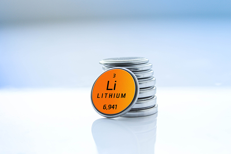
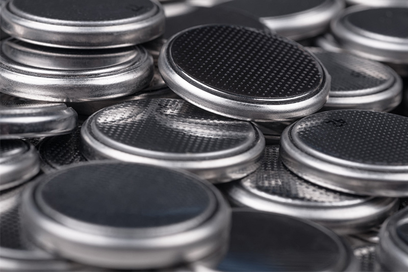
Whether you're decking the halls or buying gifts for the holidays, your preparations may involve something with a button battery. Button batteries (or disc batteries) are widely used to power a variety of everyday items around the home, such as watches, clocks, small remote controls, electronic candles, hearing aids, toys, keychains, musical greeting cards, children's audiobooks, and light-up or musical holiday decorations. These small, yet useful devices are certainly charming to look at, but they also pose a hazard that should not be ignored.


button battery


According to statistics from the Battery Ingestion Hotline, more than 3,500 people of all ages in the United States swallow button batteries each year. Although these batteries are small and usually not easy to notice, once swallowed, they can cause serious health problems, especially in children, where the consequences can be serious and even life-threatening.


Risks of swallowing button batteries

Once a child swallows a button battery, the battery releases electrical current and chemicals in the body, which can cause several serious consequences:

• Burns and corrosion: The alkaline substances in the battery can cause severe burns to the digestive tract, causing damage to the esophagus and stomach, and even possible perforation.

• Poisoning: Heavy metals inside the battery, such as mercury and cadmium, may enter the bloodstream and cause a poisoning reaction.

• Choking: If the battery gets stuck in the airway, it may cause difficulty breathing or choking.

• Organ damage: If the battery stays in the body for too long, it may cause organ damage or serious infection.

According to research, serious consequences can occur quickly within hours if a button battery is swallowed without prompt medical attention. Therefore, once an accidental swallowing occurs, parents need to react quickly and send the child to the doctor in time.


button battery


What should I do if my child swallows a button battery?

Since there is no way to know if the battery will penetrate or get stuck, it is important to seek medical help immediately.

Call the emergency center for emergency medical assistance and try to remember the time when the battery was swallowed.

Do not let your child eat or drink water to avoid food or liquids aggravating the injury. If your child swallows a button battery, do not let them vomit. This will make the reaction more severe.

Do not use nose drops or ear drops to move the battery unless instructed by a medical professional.

If the battery is still in the esophagus, an X-ray may be needed to locate it and dispose of it promptly.


How to prevent button batteries from being swallowed accidentally?

• Keep away from children: First, parents should store items containing button batteries out of reach of children. For example, place remote controls, electric toys, electronic devices, etc. in high places or lock them up.

• Choose products with safe designs: When buying children's toys and electronic devices, give priority to products with safer battery compartment designs. Some products have battery compartments with anti-tampering designs that require tools to open, which can effectively prevent children from contacting batteries.

• Check household items regularly: Parents should regularly check battery-powered devices at home to ensure that the battery cover is completely closed and undamaged. If the battery cover is loose or damaged, it should be repaired immediately.

• Educate children: As children grow up, they can be properly educated on safety to let them understand the dangers of button batteries and avoid putting them in their mouths.

• Dispose of batteries in a timely manner: If there are old button batteries at home, they should be properly discarded to avoid children's contact. For damaged batteries, parents should dispose of them in a timely manner to prevent children from swallowing them by mistake after picking them up.


The voltage drop ‌ is the decrease in voltage caused by the presence of resistance when the current passes through a resistor or conductor in a circuit.


The voltage drop is mainly caused by the following reasons.

1.‌Resistor. ‌When the current passes through the resistor, the resistor consumes part of the electric energy, which is converted into heat energy, resulting in lower voltage.

2.Current. The higher the current, the greater the voltage drop.

3.Wire length. The longer the wire length, the greater the resistance, the greater the voltage drop.

4.Wire cross-sectional area. The larger the cross-sectional area of the wire, the smaller the resistance and the smaller the voltage drop.

5.Wire material. Wires of different materials have different resistivity. The greater the resistivity, the greater the resistance, and the greater the voltage drop.


Voltage Drop will have a variety of effects on the lamp ‌, mainly including the following aspects of the impact.

1.Brightness drop. When the voltage is below the appropriate level, the brightness of the bulb will decrease. This is because the resistance in the bulb causes the voltage to be distributed to various parts, resulting in insufficient voltage, and the bulb cannot emit enough light.

‌2.Shortened life. Low voltage will cause the life of the lamp to be shortened. The lamp needs more current in the case of low voltage to emit enough light, which will accelerate the aging of the resistance, wire, circuit board and other parts of the lamp, thus shortening the service life of the lamp.

3.Flicker and burn. When the voltage is low to a certain degree, the bulb may flicker and even burn. This is because the lamp needs more current to drive in the case of insufficient voltage, and the temperature will rise, which is easy to cause short circuit or overload, resulting in the lamp burned.


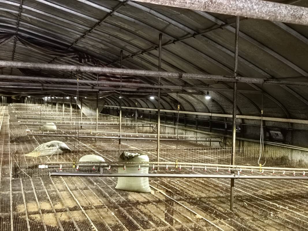
The effect of the voltage drop problem on lighting is universal, including on farm lighting. And this impact will cause direct economic losses to farmers. Is there any way to avoid this effect?


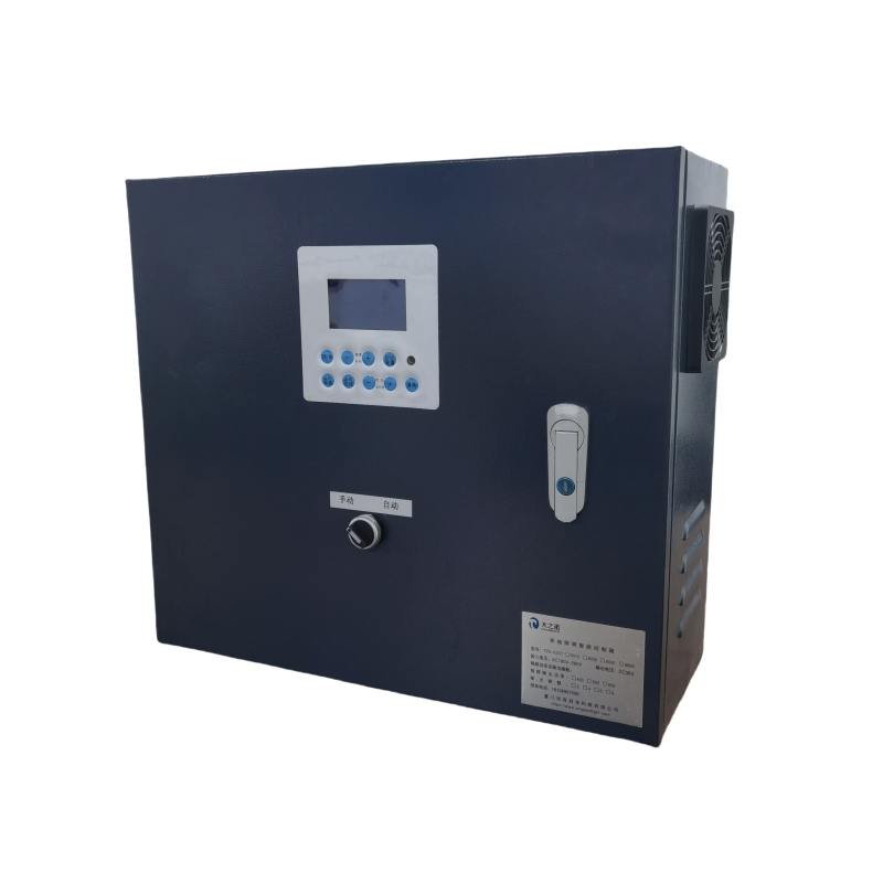
The answer is yes. After the unremitting efforts of the company's research and development team, we finally developed a Smart Poultry Lighting Control System that can not be affected by the voltage drop. The control system is equipped with self-developed drive power supply and control system. The problem caused by voltage drop to lamps has been completely solved. This control box can not only adjust the brightness and timing of the light, but also realize the sub-area control of the light. The farmers who use Intelligent Poultry Lighting Control System are extremely satisfied with the convenience it brings to the farm.


Laying hens are chickens raised specifically to lay eggs for the supply of eggs. The main task of raising laying hens is to improve egg quality and maintain or increase egg production. Laying hens breeds should be selected robust, disease resistance, foraging ability, good egg quality, high egg production rate, and coarse feeding, adapt to the local environment of the local chicken.


The laying rate of hens is very important to farmers. However, sometimes the egg production rate will decrease for some reasons, resulting in economic losses for farmers. So, what causes the decrease in laying rate of hens?


There are many reasons for the decrease in laying rate of laying hens, and the following are some of the main factors.


Environmental Factor

1. Temperature change. Too high or too low temperature can affect the laying rate of hens. For example, high temperature in summer will lead to reduced feed intake and insufficient nutrient intake of laying hens, which will affect egg production. Cold winter may cause cold stress and physiological disorders.

2. Humid environment. Excessive humidity not only affects the normal metabolism of laying hens, but also may breed harmful microorganisms and cause diseases.

3. Poor ventilation. Poor ventilation facilities or insufficient ventilation will lead to the accumulation of harmful gases (such as ammonia, carbon dioxide, etc.) in the house, affecting the health of laying hens and reducing the laying rate.


Nutritional Factor

1. Feed quality. Poor feed quality, moldy deterioration or contamination will reduce the palatability of feed, reduce the feed intake of laying hens, and lead to a decrease in laying rate.

2. Nutrient deficiency. Insufficient protein, vitamins, trace elements and other nutrients in the feed will affect the normal physiological function of laying hens, and then affect the laying rate. For example, the imbalance between calcium and phosphorus can affect the formation of eggshells.

3. Feed mutation. Sudden change of feed will lead to digestive dysfunction of laying hens, resulting in indigestion, which will affect the laying rate.


Disease Factor

1. Infectious diseases. Chickens infected with infectious diseases such as avian influenza, Newcastle disease, infectious bronchitis, etc., can lead to a sudden decline in egg production. These diseases not only affect the egg production rate of laying hens, but also can cause a large number of chicken deaths.

2. Bacterial diseases: Bacterial diseases such as colibacillosis and salmonellosis can also affect the egg production rate of laying hens.

3. Parasitic diseases: Parasitic diseases such as coccidiosis and filariasis can also have a negative impact on the egg production rate of laying hens.


Management Factor

1. Poor feeding management. Feeding is not fixed time and quantity, insufficient drinking water, equipment damage and other feeding management problems will lead to a decrease in laying rate.

2. Stress factors. Stress factors such as abnormal noise, the presence of strangers, vaccination or deworming treatment can also reduce the laying rate of laying hens.

3. Unreasonable light. Insufficient light time or insufficient light intensity will affect the physiological function of laying hens, and then affect the laying rate. 


Now, let's increase egg production in a very simple way. By using our latest research and development product High-tech Intelligent Poultry Lighting Control Box 6020 connected to the Safe LED Poultry Light Bulbs, the farming farmer can adjust the lighting time and brightness to improve lighting condition, then improve the laying rate of laying hens. 


The source of the above reason analysis: CNBIU(a Chinese We Chat Official Accounts)